Showing posts with label SE A2. Show all posts

Nov 13, 2022

GEC DA41 SE A2 amplifier Part 2

...SOLD...


Power supply

My long time favorite for smooth filtering is a LC supply. Not only the mains residual is almost a perfect sine wave, but transients response is better than with a capacitor input. With a large choke value, ripple can be very low. However, to keep first cell time constant around 15mS, the total series resistance must remains low. A well wound power transformer and equally good choke are mandatory. For that purpose, I use top quality Hashimoto’s irons for more than a decade with total satisfaction.

A first cell (25H/50µF) will reduce ripple to Vripple = Vout / 6π2 f2 LC √2, a second one (180 ohm/100µF) will floor down residual to negligible value.

Some voltage adjustment being necessary on CF anode to precisely set DA41 grid current, I splitted supply in two after the second cell. One arm to the 6K6/6V6, the second to the 6CG7.
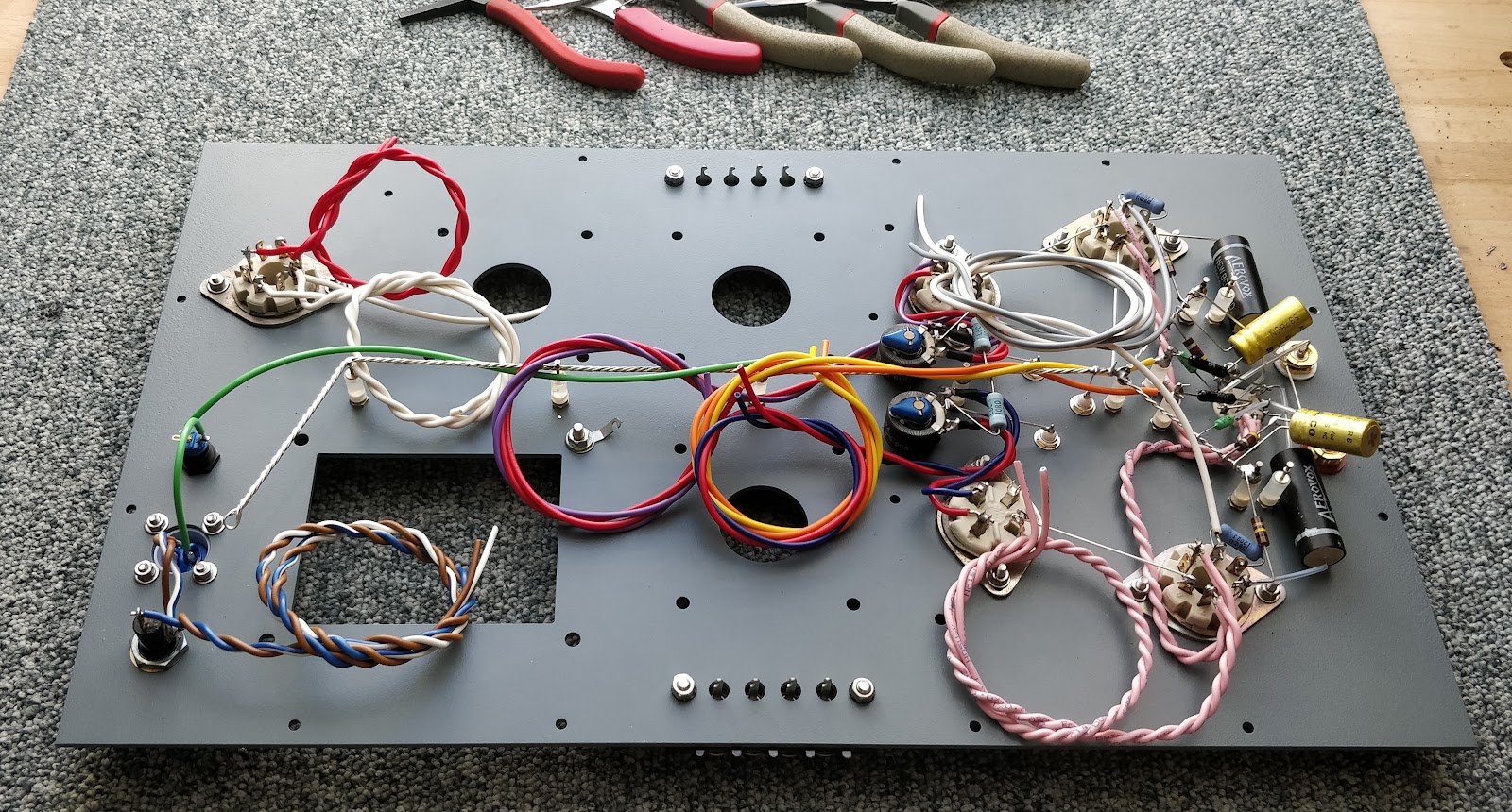
Making of

Aluminum CNC chassis, epoxy coated, plus a few components

DA41 filaments supply on sub chassis

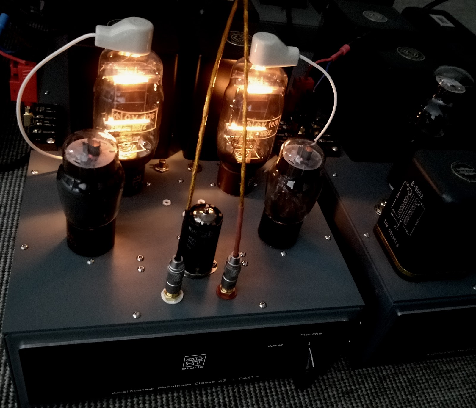
Amplifier completed, ready for measurements and listening test. It's a beefy unit weighing almost 40 pounds.

DA41 bright light is a pure enjoyment in the dark

Test setup. Max power, 100Hz_10KHz squares and THD

7,8 Vrms/8 ohm at clipping, 7,6W as expected

Despite a 18/20Kohm internal resistance the DA41 adapts quite well to the output transformer and low end roll off is not so obvious during listening test

Short reminder: transformer primary inductance has a direct effect on the low frequency response. The -3dB low frequency cutoff is determined by

FLow = Z/2πL

Where Z is the primary impedance (reflected impedance in parallel with the tube internal resistance) and L the primary inductance. For a 5Kohm reflected load and 23H@70mA inductance (Hashimoto H20-7U)

FLow = 28Hz

THD: 2,76% @ 1Watt, 6,06% @ 5 Watt. Nice harmonics distribution, mainly H2

I tried a close loop feedback between DA41 anode and 6K6/6V6 grid to get a flatter 100Hz square signal and it was disappointing. Sound became muddy, loosing all the life music could bring. Regardless of apparent poor scope results or distortion I prefer, by far, the amplifier without feedback. We must not lose sight that there is little to none relation between music, which is more in the transients domain, and squares.

Reason why it’s of prime importance to calculate accurately all time constants including power supply to respect signal ADSR.

Listening report

Garrard 301, FR24, Entré EC30, C3g phono preamplifier, 6J5 line preamplifier

On my homebrewed Klipsch Altec system the 6V6 gives the best balance with a great sense of refinement and a silky smooth sound. Each record I spin on my Garrard plays with ease and life. Dynamic is excellent, nervous or soft depending upon music. I love the way a trumpet or a sax is rendered and human voices are really addictive. Low end is firm, ample with a convincing restitution even if it doesn't extend deeply. Music is played without the somewhat harshness heard with transmitting triodes like 809 or 811. It was easy to make a comparison, the PT260 transformer can supply 6,3 or 7,5V. Is it the fact the DA41 was developed as a pure audio tube or the materials used to build it, I couldn’t say. Anyway the GEC sounds much more natural and involving than its counterparts and it blends very well with a 6V6 (Mazda or Westinghouse). The 6K6 is surprisingly more punchy with deeper bass extension, but restitution appears less natural with a forward presentation and could be a better choice on Rock music.

I am somewhat confused and surprised. To this day I don’t know which of the Visseaux A710 or the GEC DA41 is the best of my amplifiers. In any case I listen to both with great pleasure and that’s the most important. Music, music toujours…


Oct 16, 2022

GEC DA41 SE A2 amplifier Part 1

...SOLD...


Marconi Osram company, a GEC subsidiary, made some of the finest and thought after valves, from the scarce and super expensive PX family to the world famous KT one. These magnificent tubes were implemented for decades in high quality audio gears and remain today a standard in quality and reliability.

Almost every diy’er knows the KT66 and KT88, but very few the industrial DA tubes intended for high power public address amplifiers. Among these one deserves a special attention because of availability (at least for some time…), price (compared to a DA30, 60 or 100) and stunning sound quality. The DA41/CV1076.

A very fine directly heated audio triode with thoriated tungsten cathode and stamped anode (unlike the graphite one of its American relative TZ40). A pair of this powerful tube could deliver up to 175W with 5% distortion in class B push pull.

Of course such a power can’t be reached without some amount of grid current and this is probably why we don’t find much literature or schematic from experimenters. Class A2 appears to be a major obstacle for many amateurs. Implementation is not more complex than A1 if one understands the driver basics requirements.

When a grid becomes positive it acts like an anode and a few electrons emitted by the cathode are attracted by the grid. These electrons return to ground through driver impedance Zout and create a voltage drop in this load. If Zout is too high the driver is unable to raise grid to the desired voltage. Imagine a tube with 1K Zout intended to provide 10mA at +10V, it will only be able of 10V – (1K x 10mA) = 0V ! Ohms law.

Different arrangements provide current under low impedance. Shishido's way is a well known one but at the price of an expensive step down transformer, same for a choke loaded cathode follower. An interesting setup is used by Tossie Yamanaka. Very similar to a MOSFET drive, it is a power triode directly feeding the following tube grid.

This circuit is a reissue of a fully documented study by Charles F. Stromeyer (Proceedings of the Institute of Radio Engineers 24 (7), 1007-1026, 1936) and called

"General theory and application of dynamic coupling in power tube design"

...a simplified method of driving a power tube without the need of coupling devices and grid-biasing means. The power section is one whose useful plate-current versus grid-voltage characteristic is realized only with positive values of grid voltage. Its low input impedance is in series with the cathode-ground circuit of the driver tube. This impedance, also, automatically provides a negative bias for the grid of the driver, thereby eliminating external biasing. Since the electronic coupling of the two tubes varies with signal excursions, this method of amplification is termed "dynamic coupling." Practical considerations show immediately that the driver must operate into an impedance which is considerably lower than its own plate impedance. It is shown that the distortion which is produced when working with such ratios is minimized partly by making the driver circuit degenerative in order to nullify the varying effect of the driver's mu...

It’s simple, smart and works flawless. To determine operating point all we need to know is the grid current at the desired grid voltage. This is usually found in tubes datasheet.

GEC DA41 datasheet don’t give much information about grid current operation. I used the DA42 curves, a very close relative with indirect heated cathode. At Vg +25V/Va +350V, grid draws about 8mA which gives a 3K input impedance.

At that bias point, a 5K anode load appears to be the best power/distortion compromise and I can expect about 8W of great quality.

From the above statement the driving impedance must be at least 10 time lower than Zin, 20 time better. Only a cathode follower achieves this. Additionally it must be capable of some power. The simplest way could be a resistor loaded stage, this commands to raise the final tube cathode voltage with a resistor too, fully decoupled to prevent degenerative feedback, introducing a time constant in circuit and inevitably a phase shift.

The Yamanaka setup avoid this problem and collects electrons directly from the grid. Input impedance of power tube is at the same time the CF load and bias. The DA41 is directly tied to ground, no phase shift in such circuit. The main difficulty is to find a suitable tube that accommodates a 3K load, rather low, while supplying the necessary current to the final stage.

I spent some time consulting my books to find a good contender. To my disappointment very few triodes are usable and the only one that could match, a 6CK4, is hard to find in quantity (I usually pair two tubes from a batch of twelve). Best solution is a triode wired pentode. From half a dozen tested I only kept two, 6V6 and 6K6. The last one is almost unknown, darn cheap and can be considered a scale down 6F6, much better sounding. Despite its small size it’s a linear and powerful tube. Perfect for the task with 150 ohm Zout in triode mode.

Tung Sol and Visseaux, both excellent

Drawing the operating lines on Ip_Up curves seems to place the working point in a non linear region. Not the case. A cathode follower works under 100% feedback and computed characteristics are almost verticals with little curvature. Distortion remains very low. AC swing about +/-25V, enough to completely swing DA41 grid.

Really easy to implement, final bias is adjusted through anode voltage.

Such setup has a gain inferior to 1 and have to be be paired to a high gain, low distortion stage. Low distortion means high DC voltage and high load. I used the power horse 6CG7 double triode. A 150K anode resistor sets gain and a 0,025uF/200K coupling network insures good frequency transmission to the CF stage. Capacitor value can be small with a CF as input impedance is very high. In fact the grid resistor appears to be boostrapped, it’s value being multiplicated by μ+1.

Once working points, loads and DC voltages calculated the amplifier appears very simple. Three tubes, two capacitors and a few resistors.

More to come...

Oct 5, 2016

E140 SE A2 amplifier Part 3

...SOLD...


Tubes selection made, now it's time to mix up all these good things.


Before publishing amplifier schematic let's have a look to the driver limitations.

High frequency: 12B4A & Miller's effect

The input capacitance of the tube C, in conjunction with the source impedance Rg of the stage, forms a simple low pass RC filter with an upper -3dB cutoff frequency equal to:

           f = 1/(2π x Rg x C)     where     C = Cgk + Cga x (Gain12B4A +1)

The -3dB point with a 220K Rg resistor will be: f = 1/(2π x 220K x 39pF) = 18.8kHz
As I can neither reduce the load (90K _ See part 2) of the previous stage without lowering the E80CC gain nor increase Rg, some local NFB will help to keep a good overall bandwidth.
A 4 to 6 dB loop fine tuned with an FFT analyzer will give the desired bandwidth and distortion figure, definitely set by listening test.

Low frequency: inverted interstage transformer

Tamura IT is used with inverted primary / secondary coils.
In that way E140 grid current in the secondary cancels a portion of 12B4A current flowing in primary coil.
Unlike all Shishido's amplifiers working A2 all the time, this one can swing the E140 A1 where no grid current appears. This is why I have carefully chosen a 12B4A operating point where anode current do not exceed 10mA.
With such a primary current the transformer low frequency response is very good.
High frequencies are also very good without roll off with this Tamura transformer. I believe it is the way the transformer is wound that prevents attenuation when inverted connected.

Amplifier schematic


Power supplies

This amplifier requires both high and low voltage.
Low voltage is required to bias E140 grid through interstage transformer. Needs to be very steady and adjustable, a LM317 is the simplest way to achieve good regulation and very little ripple. It requires just a few parts and can be easily implemented using PCB's.


High voltage supply is a bit more complicated than usually mainly because the power stage high voltage (240V) is lower than the ones needed for previous stages (270/260V). It imposes to split the supply in two just behind the first choke keeping in mind the necessity of well calculated cells to insure good transient response. In that way I had to consider both ripple attenuation and time constant factor.

I choose choke input filter for low, almost perfect sine wave ripple and good regulation. Moreover it is less stressing for the power transformer than capacitor input filter.
Unlike capacitor input filter the ripple is not a function of current. It just depends upon voltage, choke and capacitor.
It can be calculated from formula:

           Vripple = η VHV    where    η = 1,2/LC   (L in Henries and C in µF).

In that case it will be 0,00048 x 260 = 0,125 Vcc or 0,044 Vrms and represent a 60 dB attenuation of the ripple behind rectifier (44 Vrms). Very efficient!


Amplifier is now complete. Sold to a German amateur.

Sep 7, 2016

E140 SE A2 amplifier Part 2

...SOLD...


Class A2 amplifiers need a more elaborated driver than the usual A1.

Technical approach

To source the E140 grid properly it imposes a low impedance driver stage. It is the heart of this project. I could have used a simple cathode follower directly coupled to the final triode, but to have a steady E140 operating point I had to use a well regulated high voltage supply, which I did not want. A medium power triode used as voltage amplifier loaded by a step down transformer was the Shishido way. I bought two Tamura A-8713 (20K/600) line out trans. Not too expensive they accept 20mA unbalance primary current with very decent bandwidth.
Though providing a quite low impedance path to the E140, the IT voltage ratio (1,73 10-1 or -15,3dB) commands a tube capable of a very large anode swing with low distortion. Not so many candidates. Keeping in mind the necessity of a current not exceeding 10mA trough IT (it roughly corresponds to twice the E140 grid current at maximum positive swing) the 12B4A is the tube to go. At 20K load its linearity is excellent and is able to deliver 350Vpp with low distortion, giving a driving voltage behind IT up to 60Vpp.
I do not need that much.

Back to SFR E140 triode

after a careful study of the E140 characteristics the best operating point for full power is

                                  Vak 240V, Ia 40mA, Vg +10V, Rload 5K.

It permits an anode swing of 330 Vpp with a grid swing of 40 Vpp.
The output transformer have a 4 10-2/-28dB voltage ratio, thus 330 Vpp or 117 Vrms will give 4,68 Vrms/8 ohm or 2,7W. With a dummy load the amp puts out 3,8W before clipping.
Enough for any sensitive speaker.


12B4A point of view

To get 40V pp on E140 grid the 12B4A triode must have an anode swing of
40 x 5,78 (ITvoltage ratio in that way) = 230 Vpp
The operating point will be set at

                   Ia 10/11mA with Rload 20K, Rk 3.3K, Vak 225/235V, V+ 260/270V

On the characteristics below we can see that this tube is up to the task.


First stage

this was the trickiest choice I had to make for this amplifier.
I needed a high voltage capability tube mainly because most of the A2 circuits I studied used some NFB and that I kept in mind the use of a local feedback loop between power stage and driver to:
1- get a better damping factor.
2- cancel amplitude distortion when tubes reach their extremes.
3- keep a good overall bandwidth.

To make a long story short I finally choose the E80CC among half a dozen contenders
( 5687, E182CC, 12BH7A, 6CG7...).
The E80CC is renowned for its sonic qualities and very low distortion. Many professional audio devices used this tube primarily intended for computer use.

The 12B4A needs 40 Vpp (14,1 Vrms) on grid to deliver 230 Vpp. Even with a 6dB feedback loop between the last stages the E80CC will swing the 12B4A with low distortion. Below a 150K loaded tube with a 32 Vrms (90 Vpp) output @ 1.4 Vrms (4 Vpp) input shows the high gain capabilities.


In facts DC load differs from AC. AC's one takes the next stage grid resistor Rg2 in account. In that case if I make Rg2 = 220K the AC load is about 90K. As seen below it does not change a lot the gain capability but slightly increases distortion (Philips data sheets give an output voltage of 20 Vrms (56 Vpp) @ 3,4% distortion under 250V/100K, we should be very close).
The main problem with high Rg will be Miller's effect. I will point out the incidence on 12B4A bandwidth in the next article.


Just two makers for this very fine audio tube, Philips and Tungsram.


Next episode: complete schematic, power supply and more...


Aug 8, 2016

E140 SE A2 amplifier Part 1

...SOLD...


A while ago I found some peculiar tubes that I bought for a decent price.
These E140 tubes, like the E60M, where manufactured by SFR and it was a reason for me to buy some.

SFR tubes are among the best constructed I ever saw in my life. Needless to say I knew nothing about these triodes and at that time I was not sure I could use them for an audio project.
They remained a while on a shelf till I decided to find some useful data's. Searching the web brought me very little information, not a surprise (all SFR production was intended for military use and records or data's are really unobtainable). But little was enough to catch my interest. I found that this tube was similar, at least by its shape, to a Philips transmitting triode, the TC04/10. Data's for this transmitting triode were easy to source.


I spent a lot of time plotting points to make a decent Excel Ia_Va/Vg graph that I could compare to the Philips data's.
The tubes are the same (almost) and at first sight not ideal candidates for audio use. High µ, high ρ, 10W power handling. I was a bit frustrated.
However these kind of transmitting triodes reminded me the mail I had with the late Nobu Shishido (I bought his book but did not understand a single Japanese writing and he has been very helpful in translating some parts). In the last card I received from him he explained me how to use a line out transformer to drive tubes in A2 mode with low impedance and grid current.


At that time I was just wondering about the benefits using tubes with grid current while avoiding large NFB amount to temper HF ringing and keep good overall bandwidth. Moreover in the 90' I still could find plenty of good tubes I could use A1. It was simply not my way thinking HiFi.
I was wrong.

I have today a more open mind and I decided to give a try to Nobu's approach. It was challenging as I never used tubes that way. I was in "Terra incognita". I took some time to read more about A2 modulation and decided to start this project whatever the result.
A careful look at the E140 _ TC04/10 curves shows up the very good linearity with or without current grid.


A few math later I realized that this project was feasible and I ordered parts to build an amplifier.
In this peculiar amp grid current do not flow all the time (unlike Shishido's amp) and I cannot take advantage of permanent current cancellation.
The E140 is biased such a way that the amp works A2 for a small portion of grid swing, then switch to A2/A1.
Many would think that this abrupt change will impart some sonic alteration.
Believe me it's not the case. I have bread boarded one unit and made a try with my cumbersome work, this amp sings very, very well even with the cheap parts I had on hand!
Encouraged by the results I am now waiting for high quality Hashimoto irons.

A small batch of triodes is a good idea when initiating such a project...


And to sort tubes to get matched pairs whenever possible is a good one too.


Next step, driver requirements. Stay tuned.